Sverchok is an add-on for Blender. It allows you to generate geometry in Blender in a parametric way by wiring visual nodes together rather than programming in Blender python.
This is the first of hopefully a series on very simple examples of using Sverchok. I'm learning this as I blog about it (the best way of learning something is to try and teach someone else) so if I make mistakes or find a better way of doing something later I'll try and come back and update these posts.
Installation and setup
Get the latest version of Sverchok from github.
- Download Sverchok from github https://github.com/nortikin/sverchok/archive/master.zip
- User Preferences > Addons > install from file >
- Choose zip-archive > activate flag beside Sverchok
- Enable permanently in the startup.blend using Ctrl + U and Save User Settings from the Addons menu.
My preferred layout for working in Sverchok is to start with the Compositing screen layout and change the bottom left window to a Text Editor. At the bottom of the Node Editor select the node tree type to Sverchok and add a new node tree.
Centers Polygons
Here is the first node set up we're going to look at.

This is a very simple node diagram (click for a larger image). All it does is copy one object from the scene onto the centers' of the polygons of another object in the scene.
I'll explain it in some detail to help us get a feel for how Sverchok handles the data for a mesh.
The two green "Objects_in" Scene nodes allow access to the data from objects in the scene. Select the scene object and press the "Get Selection" button to read in the data.
Each of the connections on the right side of the "Object_in" node outputs some of the mesh data for its object. To see what this data looks like connect a "Viewer_text" Text node to one of the outputs. Change one of the panels in the blender window to a text editor and select the "Sverchok_viewer" from the data block selector. When the "VIEW" button on the "Viewer_text" node is pressed the data stream connected to the node will be written to this panel.
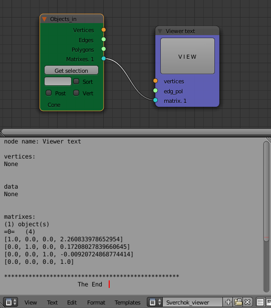
A blender mesh is described as the (x, y, z) coordinates of the vertices of the object. These are given relative to the origin of the object.
The edges and polygons describe how the vertices are connected to form the mesh. The edges are list of pairs that are connected by an edge. For instances (1, 5) means there is an edge between the obj.data.vertices[1] and obj.data.vertices[5]*. The polygons are similarly a list of the vertices connected by each polygon in the mesh.
In Sverchok it only makes sense to wire the same colored nodes together. Orange vertices coordinates to orange vertices coordinates, Green lists of vertices (edges or polygons) to other lists etc.
The matrix of an object describes the position, scale and rotation of the object. The position is given as the position of the object's origin with respect to the Scene origin. "Get Selection" the data from a simple cube and look at its matrix with a "Viewer_text" node. Move, rotate and scale the cube and compare the values in the "Transform" panel to the matrix that Sverchok displays. (You'll need to use the "Get Selection" and "VIEW" buttons to update the data after each change to the object).
A little playing will show that the location and scale are stored in the matrix
[sx, 0,  0, x]
[0, sy,  0, y]
[0,  0, sz, z]
[0,  0,  0, 1]
where x, y, z are the location and sx, sy, sz, are the scale values.
Rotations affect the 3 x 3 top left corner of the matrix. If you're interested in more detail on how transform matrices really work see these notes.
To separate out the various parts of the transform matrix use the "Matrix out" node from the "Matrix" node set. This takes a matrix (or many matrices) and outputs separately the location, scale, rotation and angle represented by that transform matrix.
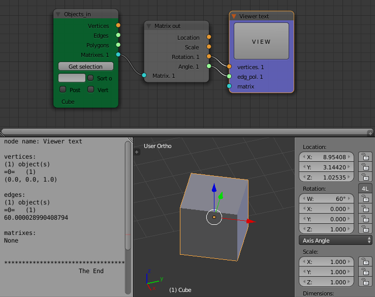
The rotation output of the node is a list of three numbers which correspond to the X, Y, Z values of the rotation given in the transform panel of the 3D view when the "Axis Angle" display option is selected. The Angle output of the node is the W value (in degrees) from the transform panel. In the "Axis Angle" mode, X, Y, Z describe an axis and W describes a angle that the object is rotated about this axis.
If you apply the transform (CTRL-A) (location, scale and rotation to the object the transfrom matrix will be reset to the identity matrix (diagonal 1s, 0s everywhere else), the origin of the object will be moved to the scene origin and the vertices of the object will be recalculated to reflect this change in origin. The edges and polygons do not need to be updated through any of these transforms as they are only lists of the connections between vertices and as such contain no positional information.
Also play with moving, rotating or scaling the mesh in "EDIT" mode. You will find that this effects the vertex coordinates but not the transform matrix.
Getting back to the "Centers Polygons" node from the "Analysers" node set. It takes a set of vertex coordinates and a list of polygon connections as its inputs and outputs data about the centers of each of those polygons.
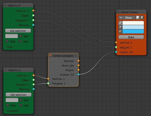
The "Centers" output of the node is colored blue, meaning its going to output matrices. In the node diagram the "Centers" output from the "Centers Polygons" node is connected to the matrix input of a "Viewer Draw" node. Connecting another mesh to the "Vertices" "Edge pol" inputs produces a copy of the second mesh at the center of each polygon on the first mesh.
Moving the second mesh with respect to its own origin will move (when everything is updated) the copies with respect to the polygon on the second mesh. The orientation of the copy is such that the copied objects z-direction is normal to the face. To see how the x and y directions map to the face select a face of the first object and change the transformation display to "Normal" mode. A little experimentation will show that the x axis of the second object is mapped to the y axis of the face normal.
The origins output of the "Centers Polygons" node output just a list of the centers of each polygon. The "Normals" and "Norm_abs" outputs are as described in the docs:
Normals is normals from global zero coordinates, vector. Norm_abs is normals shifted to centers of polygons.
To turn the output of the "Viewer Draw" node into ordinary Blender meshes click the "Bake" button on the node. If its not showing check the properties in the right hand panel.
Alternatively if a "Viewer Bmesh" node is used instead of the "Viewer Draw" node, SV will update Blender meshes as changes are made. (Still need to click the "Update" button on the right hand panel.
* I've used the python code here that you could use to access the same data in the python console.
    obj = bpy.context,active_object
    print(obj.data.vertices[1].co)